RC Servo Connectors:
A Complete Guide
by John Salt
RC Servo Connectors are basically a 3 pin/wire Dupont style connector with pin pitch (pin spacing) at 2.54 mm on center.
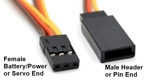
Servo connectors are not generally associated with LiPo battery connectors, however they are most certainly used for RC powering methods; namely the on board electronics (receiver and/or flybarless system and servos).
This could be either from a dedicated RX battery (NiMh, NiCad, LiPo, or LiFe), or the BEC (stand alone or built into the ESC).
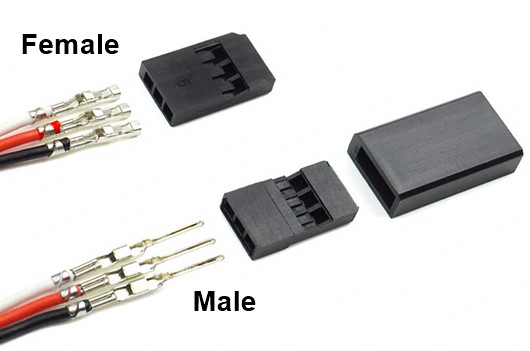 RC Servo Connector Wiring Orientation On Male & Female Connector Ends. Note: Servo Connectors are "sexed" by pin, not housing.
When used as a power plug, the three pin servo connector only uses the middle "+" pin (red wire) and the outer ground "-" pin (black or brown wire). The other outer signal pin "S" (a white, yellow or orange wire) is not used.
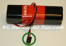 An RC Servo Connector When Used As A Power Plug Usually Won't Have The Third Signal Wire.
You will therefore often see servo connectors with only two wires going to them (generally red & black) when used as a power plug/connector.
The positive (red wire) is always in the middle of 3 pin/wire servo connectors.
This provides polarity protection or perhaps a better word is polarity immunity because regardless of the way the connector is inserted, the positive pin remains in the middle.
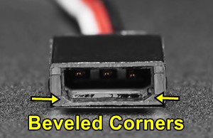 Beveled Corners Provide Some Polarity Protection
Servo connector housings are also shaped so it's difficult to plug them in backwards (beveled on two corners), but with enough gorilla force, anything is possible! :)
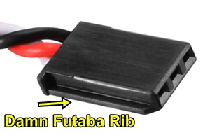 Female Futaba Servo Connector With Infamous Alignment Rib
Damn Futaba!
For the most part, RC servo connectors are universal so regardless of brand, they're all compatible, with one exception: Futaba.
Futaba in their wisdom have an alignment rib on the signal pin side of the female connector and a slot for the rib on the male connector. Pin size and spacing is however the same as it is on all servo connectors.
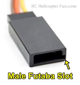
This means you can't plug a female Futaba servo connector into a standard male servo connector housing that has corner bevels because this bloody rib physically prevents insertion.
You can however plug a beveled female servo connector (no rib) into a Futaba male connector just fine.
If you ever run into this problem and don't feel like replacing the female Futaba servo connector, you can carefully cut or grind the rib off to make it "universal". I can't recall how many times I've cut myself doing this! And no, it's not because I cut all my fingers off and can no longer count to ten.
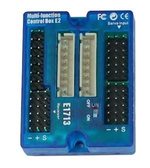 Typical Servo Control Box Only Shows The Servo Connector Orientation With Symbols & Has No Polarity Protection.
Often servo connector pinouts or headers on receivers, flybarless systems, flight controllers or servo control/distribution boxes have no connector polarity protection whatsoever.
They usually only have symbols aligned on the pinouts for the ground power and signal (- + S).
Again, this is where having the center pin of the RC servo connector being the positive/power saves the day because things are generally safe if the ground and signal pins are swapped; the thing just won't work until it's plugged in correctly.
RC Servo Connector Ratings
Servo connectors are rated for a sustained 3 Amp load, but you can easily drive them to 6 Amps for short duration. I find they start heating up with a small voltage drop after a couple minutes at 5 Amps and over. I have also peaked them over 12 Amps for a few seconds without much drama or voltage drop.
This is why we still use servo connectors on power hungry digital servos that can pull over 5 Amps on their own; but no question, in larger models with large or many, power hungry digital servos, powering the entire works off a single 3 Amp servo plug is not the best practice (I use JST RCY connectors for that).
Most folks are either feeding the servos direct power in these "large/many power hungry cases", or with another power feed going to the RX or FBL system, using higher current rated connectors, or two or more servo connectors to power the servo bus/on-board electronics.
It's not only the servo connector that's the limiting max current factor either, it's also the size of wire used with them. You generally find servo connector wiring ranging from small 26 AWG, Medium 24 AWG and large (for a servo connector) 22 & 20 AWG. Anything much larger than 20 AWG is too large to fit inside the connector housing or crimp the servo pins correctly. I even find 20 AWG a tight fit and hard to work with, so tend to stick with 22.
Anyway, if you're getting or making servo wiring harnesses for power hungry components, ensure you get 22 or 20 AWG wire and not 26 or smaller.
Learning how to crimp your own servo connectors is well worth the effort as it can save you a lot of money over the years allowing you to replace damaged RC servo connectors, make your own customized length servo extension leads & harnesses or build your own Y type servo cables/splitters.
I show how to crimp RC servo connectors in this video.
Speaking of servo connector wiring, you'll find two types: Ribbon & Twisted.
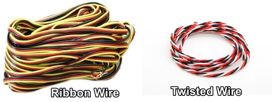
By far the most common is ribbon. I find it the nicest to work with and what I always have on hand in 26 AWG and 22 AWG sizes. However, twisted has one benefit, it's not as susceptible to interfering signal noise.
By having the wires twisted, this nullifies electrical fields that can build in the wiring, especially if a servo wire is running along a length of higher current wire for a longer distance like it can be in robotics.
This is not big problem in our hobby because our servo connector wiring runs are generally not that long; but if you ever notice you get servo glitching on a servo that has its wiring running along or in close proximity to a strong electric field, spark ignition source, or large/ higher voltage power wiring, you may want to try out twisted servo wire.
RC Servo Connector & Wiring Links
Servo Connector Purchasing Tip!
I should point out servo connectors, more so than just about any other connector type are often "miss-sexed". I too often reference them incorrectly (like in the crimping video above).
Like most connectors, the correct way to sex them is by the pins, not the housings. However, you'll often see male servo connectors being sold as female (going by the housing) and vise-versa. Look at the photos in other words to make sure you know what you're ordering and don't go by description alone.
For more helpful RC connector information & soldering tips, please see my RC Battery Connector Page.


