Choosing the Right RC Battery Connector:
Types, Applications, & Soldering Tips
by John Salt - Last Updated March 2025
"What RC battery connector should I use & how to solder it" are two of the most common questions I get asked. I figure it's time I devote a page to these little rascals along with some RC connector how to soldering videos.
My RC Soldering For Beginners page covers soldering questions and soldering equipment in much more detail.
But let's start with the RC battery connectors themselves...
RC Battery Connector Types & Styles
Choosing One Based On Current Handling Ability & Personal Preference Is Key.
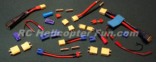
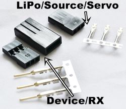
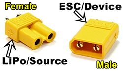
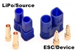
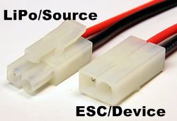
As shown in the above photo, there are all sorts of flavors and sizes of RC battery connectors
out there and that photo only shows a small smattering. So which one to use can be a complicated decision when you are first
starting out if you don't know much about them yet. I hope this page
helps you with that :-)
The purpose of all these RC LiPo Battery connectors is simple. They offer a convenient & easy way to connect our RC LiPo battery packs into our model's ESC/Power system to complete the electrical circuit, allowing the current to flow from the Battery to the ESC and/or other electronic systems/components.
Most RC connectors are polarity protected, meaning it's very hard if not impossible to plug them in backwards which goes a long way to save expensive electronics from letting out the magic smoke.
The connection must be reliable, solid, and able to pass enough current to meet the maximum current demands of the model. If the RC LiPo battery connector can't pass enough current, it can overheat and/or introduce a voltage drop.
Overheating only occurs if the over current condition lasts for a sustained period of time; so short over-current bursts, even double of what the connector is rated for, are not going to cause a hot & melted connector. A voltage drop on the other hand which could occur in such an instance, can also cause bad things to happen such as restarts to microprocessor controlled electronics (modern day ESC's, Receivers, and flybarless systems) or voltage spikes/ripple.
This is pretty much the first thing you have to know/understand in order to choose an adequate connector for your RC powering application, the amount of current it can pull. Your motor/ESC combination or RC model should indicate maximum current ratings and that is usually a good place to start.
If for example your motor & ESC have a maximum sustained current rating of 50 Amps, then you should be looking at LiPo connectors that have a sustained/continuous 50 Amp rating or better. There are of course "real world" exceptions to this which I talk about later in this article; but to keep things simple, this is how you first consider what size/current rating connector to use.
I
say size, since the size of the connector goes hand in hand with how
much current it can pass. The larger the connector, you guessed it, the
more current it can safely pass through the pins. The reason being, the
more surface contact area the pins have, the more electrons they can move;
exactly the same as the larger the wire, the more electrons it can move.
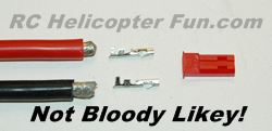
Another tip-off here is if your LiPo battery or ESC has very large wire, chances are you will be pairing it with a large connector.
RC Battery Connector Styles
After knowing what current rating/s you need, things become more personal when choosing a specific style of connector.
After all, there can be several styles of connector with similar current ratings, so how to decide?
When first starting out, it may be as simple as using the connector type that came with your RC model or LiPo battery.
But sooner or later as you progress, chances are you'll be limited to battery brands as well as other limitations by only using stock connectors.
You may also find you don't like a particular connector for one reason or the other such as it being more expensive, shorter life span, being harder to solder or replace than another style connector, or substantially harder to plug & unplug.
Incidentally, a stiffy connector type should not send one running. This also usually means the contact is uber strong; but it can also be a royal PIA if it's so bloody skookum, it's a proper nightmare to use. Again, this is individual choice.
The other little bit of advice I can give about choosing a specific style over another is getting one type of connector for your various current ratings and sticking
with it.
This way, all your connectors in that current rating range will be the
same as will your charging plug/s and/or Para-Boards
saving you the hassle and cost of having to have several different
types of charging plugs/cables/boards. This also allows you to have a supply of "same" spare
connectors on hand for when they wear out, or if you damage one.
Below is a list along with links to the most common LiPo connectors on the market right now (there are certainly many more), but these are the most popular ones "currently" out there. :-)
I have broken them down into four size groupings based on their current ratings (lowest to highest).
What style you end up getting really boils down to personal preference or what you already use, but I do give some thoughts about each style type based on my own experiences.
Micro RC Battery Connectors (1-10 Amps)
Click Here To Learn About Micro Deans Connectors (also called Deans Mini, Deans Micro and Mini T-Plug).
Small RC Battery Connectors (10-30 Amps)
EC2 connectors are rated up to 20 Amp sustained loads, with up to 30 Amp bursts.
They use 2mm bullets and are basically a smaller version of the vastly popular mid size EC3, and large EC5.
Like both the EC3 & EC5, wiring is first soldered into the pins which are then snapped into the case when cooled down and require no heat shrink insulation as the solder connection is hidden withing the connector housing. This makes replacement/reuse more difficult.
I find EC2's are not as hard to plug & unplug as their big brothers are, and if you have a 10 to 20 Amp RC powering requirement, EC2's are a solid choice in a compact size.
See my EC3 soldering video further down on page for same basic soldering method.
Regular size Tamiya connectors rated at 15 Amps maximum were once very popular, especially with the electric RC car, truck, and boat crowd; but since high Amperage LiPo's have entered the scene, Tamiya plugs are used less and less these days.
They are quite large for the small amount of current they can handle. You will however still find them powering smaller models and some types of nitro
starting systems. Most 7.2V (6 cell) C size NiCad and NiMh packs to this day come standard with the Tamiya connector installed.
Tamiya connectors are easy to plug/unplug and have a sprung locking tab which not only keeps the connectors from pulling apart once engaged, but also gives added "paw grip" when pulling the plugs apart as the tab is disengaged.
They required crimping the wire to the pins but you can also get them with the wires already crimped allowing you to just solder the wires to your device or battery.
Medium RC LiPo Connectors (30-70 Amps)
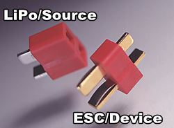
The Deans Or T Plug Type Connector
Click Here To Learn About Deans Connectors including the Deans soldering video.
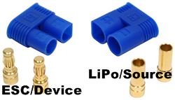
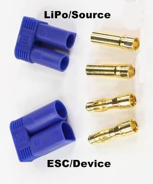
EC3 Connectors use 3mm long bullet pins and are rated for up to 60 Amps of continuous load, 75 Amp burst.
Horizon Hobby use the EC style connectors pretty much exclusively, and have made them very popular in their eFlite & Blade line of airplanes and helicopters.
These are therefore the very first LiPo battery connector many are introduced to, myself included. One of the biggest complaints with EC3's by myself and others is they can be very difficult to plug/unplug, at least compared to the other connectors in this current range, not to mention they are fairly pricey.
Wires are soldered into the hollow end of the pins and then the pins are snapped into the connector so no worries of melting the plastic housing. Another advantage is the EC's don't require heat shrink insulation as the wire insulation runs into the connector housing which is nice. The draw back is it can be difficult to remove the pins from the housing for replacement or reuse. I find a small drift punch while supporting the housing on the edges so the pins can be tapped out the back side will work most times (but not always).
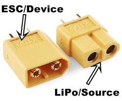
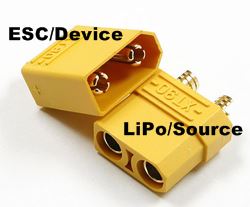
XT60's as I already stated are one of my favorite RC LiPo battery connector / s in this current range and I use them even on fairly large birds without issue. They are rated for 60 Amps sustained and 90 Amps for short bursts (why I can get away using them on larger models that are not flown too aggressively).
They are fairly easy to plug/unplug and why I like them better than Deans or EC3's.
Like I mentioned in the XT30 description, the genuine Amass ones are constructed out of high temperature nylon so they don't melt/pins loosen if you get a little carried away.
External soldering "cradle style" pins on the back require heat shrink insulation, but make them easy to remove/replace/reuse.
See my XT90 soldering video further down on page for same basic soldering method.
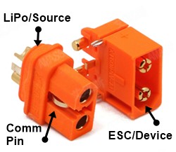
Another "flavor" of the the XT60, is the XT60i. These connectors are fully compatible with XT60's, but they have a 3rd contact pin (comm pin indicated in this photo).
This communication pin is used with the BattGo Smart Battery System as the communication port to send information from the battery to the ECS or charger or vise versa.
As you may know from my best RC charger page & best LiPo battery page, I'm not a fan of "Smart" battery technology; but if you have such a battery or model that uses it, this is the type of plug you MUST replace it with. In fact, there is another reason not to like smart battery technology, it also limits your connector options. Soldering is also a little more difficult with the extra pins to solder up along with the main ones. :(
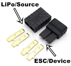
As the name suggests, Traxxas battery connectors (TRX connectors) are used exclusively on electric Traxxas RC vehicles/boats but can be fit to any current application up to about 60 Amps.
These are a very nice connector that many
say are one of the nicest to plug and unplug. I just tried a set out and am very impressed with the ease of connectivity. They use a flat contact tab like Deans over a bullet style connector pin.
Like the EC3 connector, the Traxxas connectors don't require heat shrink for insulation as the wires are soldered onto the ends of the contact tabs and inserted deep enough into the connector housing afterward that the wire insulation offers full protection, also prevents melting the connector housing. Similar to the EC style connectors, pin removal can be very difficult without a special pin release tool/key.
TRX connectors are also one of the most difficult to solder properly because if you let even a small amount of solder wick down the connector tab, it will prevent the tab from clicking into the housing correctly. This is where good tinning skills and quality solder really come into play for a sort duration solder melt. Just enough heat to make a solid mechanical & electrical bond without enough heat migrating down the pin cause the solder to flow down as well.
Large RC Battery Connectors (70 Amps & Up)
EC5 Connectors are a larger/ longer version of the EC3 and because the bullet pins are longer (5mm) they have an even greater surface area for contact. EC5's are rated for up to 120 amps of continuous load, and bursts of upwards of 150A. Perfect for large 1/4 scale electric planes, 80mm+ EDF jets, and 700-800 size electric helis.
Like the EC3's, the wires are soldered into the back of the pin and pushed into the housing far enough that heat shrink insulation is not required, but pin removal afterward is very difficult for replacement/reuse. My drift punch method on EC5's is seldom successful and I generally destroy the housing or the pin in the process.
The EC5 Lipo battery connector used to be the only large current connector I trusted on my larger 12S powered 700 & 800 helicopters, but I've completely switched over to XT-90's after a crash which I talk about later on in this article under the heading "connector life span".
See my EC3 soldering video above on page for same basic soldering method.
The Amass XT90 is rated for a continuous 90 Amp load with bursts up to about 120-130 Amps.
As I just mentioned above, I've converted my EC5 batteries & ESC's over to the Amass XT-90 RC LiPo battery connectors. I've been using these high current connectors long enough now (5 years) to confidently say I like them better and that they are performing & lasting longer than the EC5's did on my larger models.
Soldering connections on the back side of this plug are exposed so heat shrink must be used; however, there are now versions of this plug that have a plastic insulation cap that snaps on the back end of the plug if you don't want to use heat shrink.
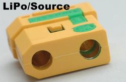
Another AMASS XT-90 RC battery connector option is their "anti spark" version (XT90S). If you look closely at the inside of the right contact tube in this photo, you can see the very first section of the tube is split and insulated from the rest of the contact tube.
This initial split section is wired to an internal resistor which allows the electrolytic power capacitors in the ESC to charge up before the rest of the pin makes contact as you insert it. This eliminates that big connector SPARK as the capacitors first charge up (basically acting like a dead short for a fraction of a second) before the main connection is made.
I admit, I kinda like that big spark when plugging a LiPo into the ESC because it means the caps in the ESC or external Cap Pack are nice and healthy, but it does pit and wear out the connectors faster - no question. It's also potentially damaging the capacitors themselves over time. This is why I have recently started converting all my female (battery/power side) XT90's to these anit-spark ones and must say - I really like them. No more carbon pitting!
The downside is these anti-spark connectors are a little more expensive and they are on the battery side, so you generally need a lot more of the more costly female plugs than the cheaper male plugs that are on the ESC side. The other caution with them is you have to make sure you plug them all the way in.
That goes without saying, but I had a bad habit (still do) of just barely plugging in a connector at times when I'm programming my ESC's if for whatever reason I have to quickly pull the connector apart. When you do that with these anti-spark connectors and only the upper portion of the contact pin (the one with the resistor) is conducting all the current, the resistor in the connector can get very hot and can destroy the connector! Yep - I learned this the hard way :)
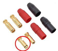
Amass AS150 Anti-Spark RC connectors are quickly becoming a "favorite" for high voltage & current RC powering applications.
They use 7mm bullets and as the name suggests, are rated at 150 Amps (190A burst).
One of the male bullets is special, it's the one circled in red.
If you look closely. It has an end cap that is insulated from the rest of the pin. This is the last plug you connect when you connect your battery to your ESC.
That insulated end cap is connected internally through a resistor to the main body of the pin to slowly charge the capacitors in your ESC as it first makes contact with the female bullet; preventing the big spark when connecting - it works surprising well. Unlike the XT-90S, this more costly pin can be placed on the ESC side to keep costs down.
The female side of the bullet is actually the split connector (unlike most bullet pins), and uses a sprung clip around the edge to maintain proper contact pressure, even after hundreds of cycles.
These connectors are separate and therefore take up a little more space than a contained 2-pin connector type, but as they are used on large RC aircraft, room is rarely an issue. These connectors don't require heat shrink after soldering for insulation; the insulated end caps are simply threaded onto the bullet pin - nice design.
A little costly at close to $10 for a set (2-pairs), but considering they don't wear out from sparking, long term savings have to be taken into account.
See my Bullet soldering video below on page for same basic soldering method (less the heat shrink application).
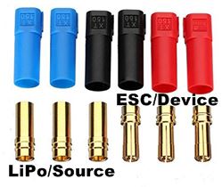
Genuine Amass XT150 connectors are rated at (you guessed it), upwards of 150 Amps. I can't find any burst ratings on this connector but like with most, I suspect it's about 25% more than the continuous rating.
These are BIG connectors using a 6mm bullet so you need adequate room. One neat thing with them is the individual plugs can be slid together to make a one, two, or three pin connector. This can make these big plugs a little easier to work with in tight areas where having two slid together would be too bulky.
See my Bullet soldering video below on page for same basic soldering method (less the heat shrink application).
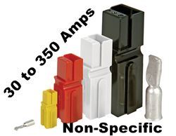
Anderson Powerpole connectors are a long time proven industrial electronics connector that has filtered down into the world of RC. They are pretty much the most expensive connector listed on this page; but I have to tell you, the housing quality is one of the nicest.
They are super easy to plug and unplug, but the connection is not that tight I have found. Crimping is the preferred wire attachment method (with the correct crimping tool), but they can be soldered if you're careful. The pin is held into the connector after crimping or soldering and doesn't require heat shrink for insulation.
They are a fairly big and heavy connector compared to RC quality ones in similar Amp ratings, and don't offer fool proof polarity protection (can be plugged in backwards when not clipped/stacked together in the correct orientation). Powerpole's come in several sizes ranging from the small PP10 up to the massive PP350 which is rated at 350 Amps.
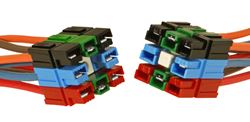
As you can see, Powerpole connectors are "stackable" and can be clipped together in many different configurations (they are the Lego of connectors).
Because they are designed for industrial electronics use, there is better data sheets on all the various specifications available on Anderson Power Products web site.
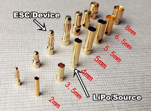
Last up we have stand alone "Bullet Style" connectors, sometimes also called "Banana Plugs". Various sizes (measured in diameter) for various current ratings.
Listed below are some approximate continuous current values based on bullet size. There are of course variations dependent on bullet length (more length = more contact area) as well, but this list should get you in the ballpark for most of them.
- 2.0mm Bullet = 25 Amps
- 3.0mm Bullet = 50 Amps
- 4.0mm Bullet = 100 Amps
- 5.0mm Bullet = 120 Amps
- 5.5mm Bullet = 130 Amps
- 6.0mm Bullet = 140 Amps
- 6.5mm Bullet = 150 Amps
- 7.0mm Bullet = 160 Amps
- 7.5mm Bullet = 175 Amps
- 8.0mm Bullet = 200 Amps
Most of the RC LiPo Battery connectors I have listed above (other than the few that use flat tab contacts), all use bullet connectors within the housings. However, some folks just like to use stand alone bullets as they are less expensive without the housing, weigh less, and take up less room.
I use stand alone bullets pretty much only for ESC to brushless motor connections (3 used), and would much rather have a nice housed connector on my LiPo packs and ESC's for ease of connectivity and safety. It's much easier for example for stand alone bullets (even when coated with heat shrink) that are not housed in a connector housing to short out.
There are essentially two styles of male bullet connectors, split & sprung. In the above photo, the male 2 to 5mm are the sprung design, the 5.5 to 8mm are the split type. The female side are all the same, basically a hollow tube that the male end fits into.
The sprung connectors have a sprung sleeved section that wraps around the inner pin and that is what makes contact with the inside of the female tube. The split style has the pin divided into two or more quadrants that are sprung outward, slightly wider than the internal diameter of the female end. As they are plugged in, the "quadrants" are squeezed and held tight again the inside of the tube under tension making good electrical contact.
Generally speaking, the split style are able to handle larger current loads than the spring style. I talk about one "hidden" weakness that all spring sheathed bullets have after the next section of this article.
Sexy RC Battery Connectors
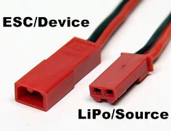
You may recall I mentioned "Male" & "Female" a few times while describing some of these various connectors above. You may have also noticed in most of the above "connector type" photos, I show one sex of connector as the LiPo/Source, and the other as the ESC/Device.
Why is this important?
Basically, any connector that has power at the pins (ie. the one on the battery side or BEC side), must be the one out of the two that is the least likely to short out. This is very important for safety reasons and I have often seen people new to the hobby solder the wrong sex on the wrong end.
This will still work of course, but you risk shorting out the LiPo pack if you solder the easy to short connector on the battery side instead of the device side.
So which is the least likely to short?
A little common sense is all that's required to figure it out. Simply look at each plug end and figure out which one is easier to accidentally contact both pins at the same time (shorting them out) with a metal or electrically conductive object, such as the tip of a screw driver that might be floating around in your RC field box along with several battery packs.
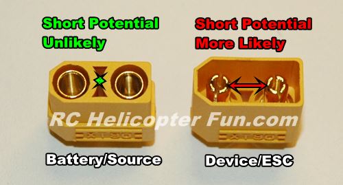
No question you
could short the other connector out with something like a bare wire bent
in a "U" shape, or pair of needle nose pliers / tweezers inserted into
each insulated pin, but it's much less likely to occur.
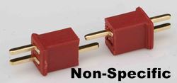
This is why most people in the hobby don't care for the non-specific plugs that can be used for both source and device. Even with them however, there is a safety rule that must be followed. The exposed pin on the battery side must always be the negative "-" and the encased pin must be positive "+".
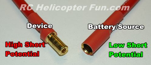
Same
holds true for exposed bullet pins. The female bullet that is insulated
with heat shrink will always be on the power side and the exposed male
pin will be on the device side.
RC Battery Connector Life Span?
Main power plugs/connectors have a finite cycle life (how many times they can be plugged & unplugged) before they start wearing out, pitting & carbon burning from ESC capacitor charging arcs, oxidation, dirt, or the spring tension of the contact points starts getting weak.
All conditions or a combination will give you an increasingly poor connection with increased resistance over time. This generally starts showing up as power drop-offs or worse, cut-outs & restarts under high current loading meaning it's time to replace your connectors. Yep, I've been there and have the sad remains of the heli as a reminder!
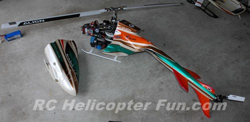 Hidden Carbon Pitting In The Male EC5 Connector Took My Beloved "Sharky" Out Of The Sky.
Why did this happen and what is the RC connector lesson to take away from this crash? As it says above, a hidden problem with the male sprung bullets in the EC5 connector.
Because spring bullets have a sleeve that wraps around the main body of the pin, there actually is not that much contact area in relation to the length of the pin. Only the small top and bottom area of the sleeve are in direct contact with the inner pin.
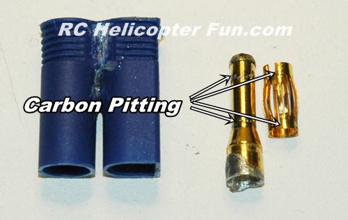 EC5 Hidden Carbon Pitting Reviled Once Spring Sleeve Was Removed
In addition to a rather small "contact patch", this area is completely hidden from view. In fact, this is the very last connector I pulled out to check because on the outside, it looked practically new, and was still very stiff to plug/unplug. Only when I decided to pull the sprung sleeve off did I notice the significant carbon pitting on both the top and bottom of both pins where the sleeves make contact.
I still get sick to my stomach thinking about how a $2 connector destroyed a rare Blackshark F3C fuselage and why I didn't catch it before hand considering my almost obsessive maintenance regiment. Of course this had to happen when I was way out at one end of the field over a large stand of pine trees as I climbed to do a half cuban 8.
The ESC powered down as I was pulling almost full collective, and I
didn't have the altitude or height to auto back over the the safety of
the field. If something bad is going to happen, it will usually do so at
the most inopportune time.
I later confirmed several voltage drops and then the big one that powered down the ESC by looking
at the Castle Link flight log data (a wonderful tool). Thus the search
& checks of all battery wiring and the connectors, only to find the very
last one on the ESC was the issue even though it looked perfectly fine. I have
since talked to three other people who have been experiencing power
drops and coincidentally, all were using sprung sleeved bullets. Upon
inspection, the same hidden carbon pitting was verified.
This is why I've converted all my EC5's over to XT90 and XT90s anti-spark connectors. XT90's are a "split pin" type so there is no hidden part of the pins and they have a larger contact area. I'm not saying the EC5 or sprung bullets are bad connectors, but I certainly won't use them anymore due to both my and others anecdotal experiences.
If you use sprung sleeved bullets however, it would not hurt at all to pull the sprung sleeves off the male pins to inspect for hidden pitting underneath every now and then; especially if you are getting the odd power drop while pulling higher current loads during a flight/drive.
Only problem with that is once you remove the sleeve, it will generally be a loose fit afterward over the pin. Compression pressure when it's slid into the female end should then hold it tight & make good contact; but I would be somewhat worried about a subsequent increase in resistance.
So, think of all these larger RC LiPo battery connectors as "wear & tear" items and keep a watchful eye on them.
I say primarily the larger ones because they handle more current, are stressed more, and often arc when plugged in. You don't see the same wear & tear with a smaller RC battery connector for example in most cases. Some of my smaller Servo & JST RCY connectors are over 15 years old and working like champs still.
Regardless, replacing RC battery connectors when they start looking worn or are getting really "easy" (loose) to plug and unplug is cheap insurance considering what can happen if they go ignored
Two other things I want to stress here:
- Maximum current connector ratings are when the connectors are brand new; all RC connectors (especially the larger high current ones) will generate increasing resistance which decreases their current ratings as they are cycled over time.
- The RC LiPo Battery Connector is almost always the weakest link between the battery and the ESC or the ESC & the motor. In fact, I actually prefer to solder my ESC to motor connections if at all possible. No question, I would like to do that between the battery and ESC as well, but that of course is not practical. The more connection points, the more weak links you introduce into your power system. This is why I strongly recommend against using converter connectors, as they introduce two or more extra connection contacts.
Learn to solder RC LiPo battery connector / s in other words so you don't have to waste money on "weak links".
Choosing An RC Battery Connector Amp Rating In The Real World
To finish off here and before getting to the two main soldering videos, I will leave you with one last little bit of advice based on my RC battery connector experiences over the years.
As I mentioned at the beginning of this article, theoretical max amp ratings are to be used as a guide only when choosing one connector over another. As we have already seen, there are variables that will affect your actual maximum current needs.
As
just one personal example, I'm not a power hungry electric 3D smacker. I
learned to fly these egg beaters on nitro power and managing your rotor
energy was and is an essential part of flying. In short, I rarely even get to
1/2 of what my electric helicopters can pull in terms of maximum power.
That is why I can safely fly a 700 size electric heli with a 60 Amp
rated connector and never have a problem. Rarely will I see more than a few short bursts even close to 100 amps on my 700's; most of the time, they
are sipping about 40 to 50 amps max.
On the flip side, a high rated connector could be faulty, have a poor solder job, or coming to the end of it's useful life and not able to pass even 1/4 of the current it's rated for (my ESC 5 experience above is just one such occurrence).
So how to decide what your real current needs are?
Data
logging ESC's that show current draw, external data logging power
meters, and current sensing telemetry sensors are all wonderful tools to help you determine your "ACTUAL" powering
needs based on hard facts.
I'm very much partial to data logging ESC's as they give you the "big electrical picture" as to what is going on; not just current, but voltage drop, and ripple which are all helpful measurements for sorting out or determining RC LiPo battery connector issues.
As was already touched on, a less technical way, but certainly workable, is feeling your RC LiPo battery connector for warmth right after a hard flight or drive. No RC LiPo battery connector should be getting any warmer than the wires feeding it (basically not warm at all) during use. If it is getting warm, there is a voltage drop occurring across the pins. This method won't detect short term over current bursts, but it's better than checking nothing at all.
At the end of the day, get the right RC LiPo battery connector for your needs. The best connector current rating is the one that handles your specific power requirements with some wiggle room to spare as the connector ages and the resistance increases a bit.
More RC Soldering Tips Videos
Below are three videos going over soldering equipment, tinning wire, and splicing wire.
